Expansion Header (GPIO/SPI/I2C/UART/SWR/I2S)
The MitySOM-QC6490 Development Kit has 2 expansion headers, J21 and J22, located on the bottom side of the Development Kit PCB.
Several peripheral interfaces are available via these expansion headers.
To see which interfaces are available on each pin, refer to the MitySOM-QC6490 Development Kit Datasheet and the MitySOM-QC6490 DataSheet
Development Board Configuration
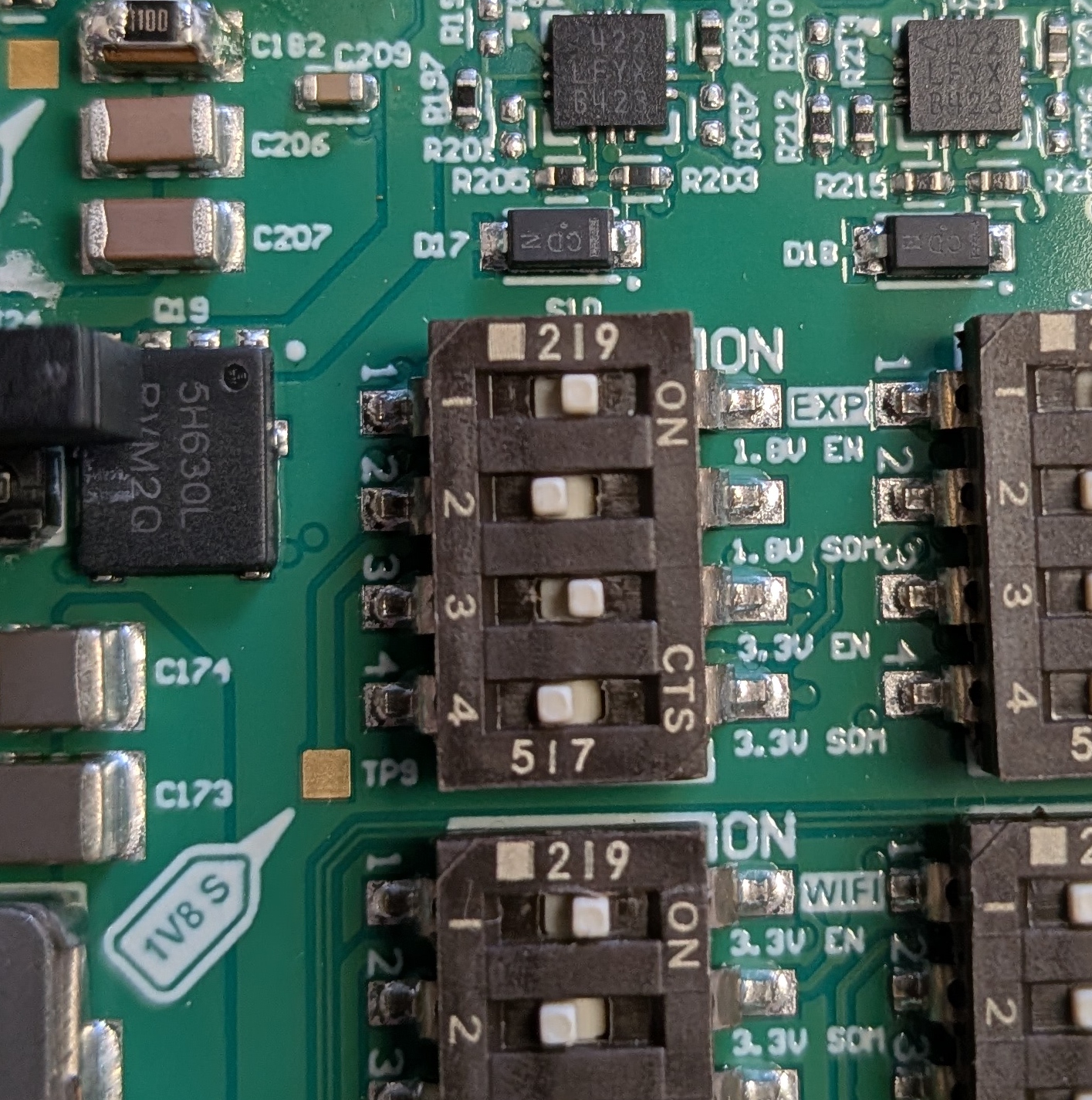
Ensure that Switch S10 is set properly.- Switch 1 should be set to enable EXP, which is a top level enable for the 1.8 V expansion supply
- Switch 2 can be either set or not set
- If Switch 2 is not set the 1.8V comes from the DC supply on the Development Kit
- If Switch 2 is set the 1.8V comes from the SOM
- Switch 3 should be set to enable the 3V3 expansion supply from the DC supply
- Switch 4 should NOT be set for Rev 1 or 2 of the Development Board as 3.3V from the SOM may actually be a higher volage. See MitySOM-QC6490 Development Kit Datasheet for further details
- For Rev 3 onward, Switch 4 can be either set or not set.
- If Switch 4 is not set the 3.3V comes from the DC supply on the Development Kit
- If Switch 4 is set the 3.3V comes from the SOM
- For Rev 3 onward, Switch 4 can be either set or not set.
GPIO Control
libgpiod
The libgpiod tool is the recommended way to control and monitor pins configured as GPIO. There are bindings for C++ and other high-level languages, as well as command line tools like gpioget and gpioset.
Note: libgpiod is currently not persistent, meaning that any pin states that were modified are not guaranteed to remain in the same state after program execution finishes.
- The
gpioinfocommand will print out the all of the GPIO pins, including the names for pins that have them assigned. All of the GPIO pins on the expansion headers have names assigned.
- The
gpiosetcommand can be used to set pins to output high or low, for example: set GPIO_16 high withgpioset GPIO_16=1.
Line bias can be set with the-boption, Ex:gpioset -b pull-up GPIO_16=1
The command can be run with with the-zoption to run it as a background process and keep it active:gpioset -z GPIO_16=1
Note: thegpiosetutility is not persistent, meaning that the assingment only remains in effect for as long as thegpiosetprocess is active. libgpiod is currently adding support for persistence via the gpio-manager user space daemon.
- The
gpiogetcommand can be used to set pins to input and read their value, ex: read GPIO_16gpioget GPIO_16
In order to read the value without changing the pin to input, use the-aoption.
gpiomonwill set the pin to input and print edge events as they are detected.
gpiodetectwill print out the gpiochip info, the chip numbers refer to the following units:gpiochip IC 0 PM7250B 1 PM7325 2 PM7350C 3 PMK7325 4 QC6490 5 LPASS LPI TLMM
More info on the libgpiod command-line tools can be found here.
sysfs
Alternatively, the legacy sysfs method can still be used with to control the GPIO pins (with persistence).
Details of user-level access are given in https://www.kernel.org/doc/Documentation/gpio/sysfs.txt. What follows is a brief sampling of what can be done.
You can print GPIO info, including the index of the desired pin, by mounting debugfs:mount -t debugfs none /sys/kernel/debug, and reading /sys/kernel/debug/gpio.
Note: The GPIO line names are not shown in this file, but it can be cross referenced with the output of gpioinfo to determine the index of the desired pin.
Assume we want to access the GPIO at index 563.
- Making the GPIO accessible from user-space.
echo 563 >/sys/class/gpio/export
- Input GPIOs
- Setting the direction of the GPIO for input
echo in >/sys/class/gpio/gpio563/direction
- See the current value
cat /sys/class/gpio/gpio563/value
- Setting the direction of the GPIO for input
- Output GPIOs
- Setting the direction of the GPIO for output
echo out >/sys/class/gpio/gpio563/direction
echo high >/sys/class/gpio/gpio563/direction  # sets direction and initial value
echo low >/sys/class/gpio/gpio563/direction
- See the current value
cat /sys/class/gpio/gpio563/value
- Set the current value
echo 1 >/sys/class/gpio/gpio563/value
- Setting the direction of the GPIO for output
- Checking the direction
cat /sys/class/gpio/gpio563/direction
- Stopping access from user-level
echo 563 >/sys/class/gpio/unexport
Reconfiguring the QUP pins
Please see Configuring the QUP Ports (I2C I3C SPI and UART) for further details.
Enabling the RTC clocks
WIP. Enabling the RTC clocks on J22 pins 5 and 19 requires rebuilding the firmware and will be detailed in the future.
Using the SMB pins for an additional charge pump IC.
WIP. Details on using the SMB will be provided in the future.
Using the EXP power pins
The 1V8-EXP and 3V3-EXP pins provide power output on the expansion header. The power rail source can be configured to either come from the devkit baseboard power output (e.g. 1V8-DC), or the SOM power output (e.g. 1V8-SOM).
This is configurable by either hardware or software, with software control taking precedence. For more information on power output, reference the MitySOM-QC6490 Developmnet Kit Datasheet.
- Enable the 1V8-EXP power output by setting the DIP switch S10-1 to the ON position.
- Change the 1V8-EXP power source to 1V8-SOM by setting the DIP switch S10-2 to the ON position. (The 1V8-DC power source is selected by setting it to the OFF position).
- Enable the 1V8-EXP power output by setting the 1V8-EXP-EN GPIO pin to HIGH:
gpioset -z 1V8-EXP-EN=1
- Change the 1V8-EXP power source to 1V8-SOM by setting the 1V8-EXP-SOM GPIO pin to HIGH:
gpioset -z 1V8-EXP-SOM=1
(The 1V8-DC power source is selected by setting it LOW).