Getting Started
The purpose of this page is to provide a user with all the details they need to get started with the MitySOM-QC6490 Development Kit
If you have any issue please make sure to post in the forums so that we can provide support.
Handling the SOM
 Please take the following into account when handling the SOM
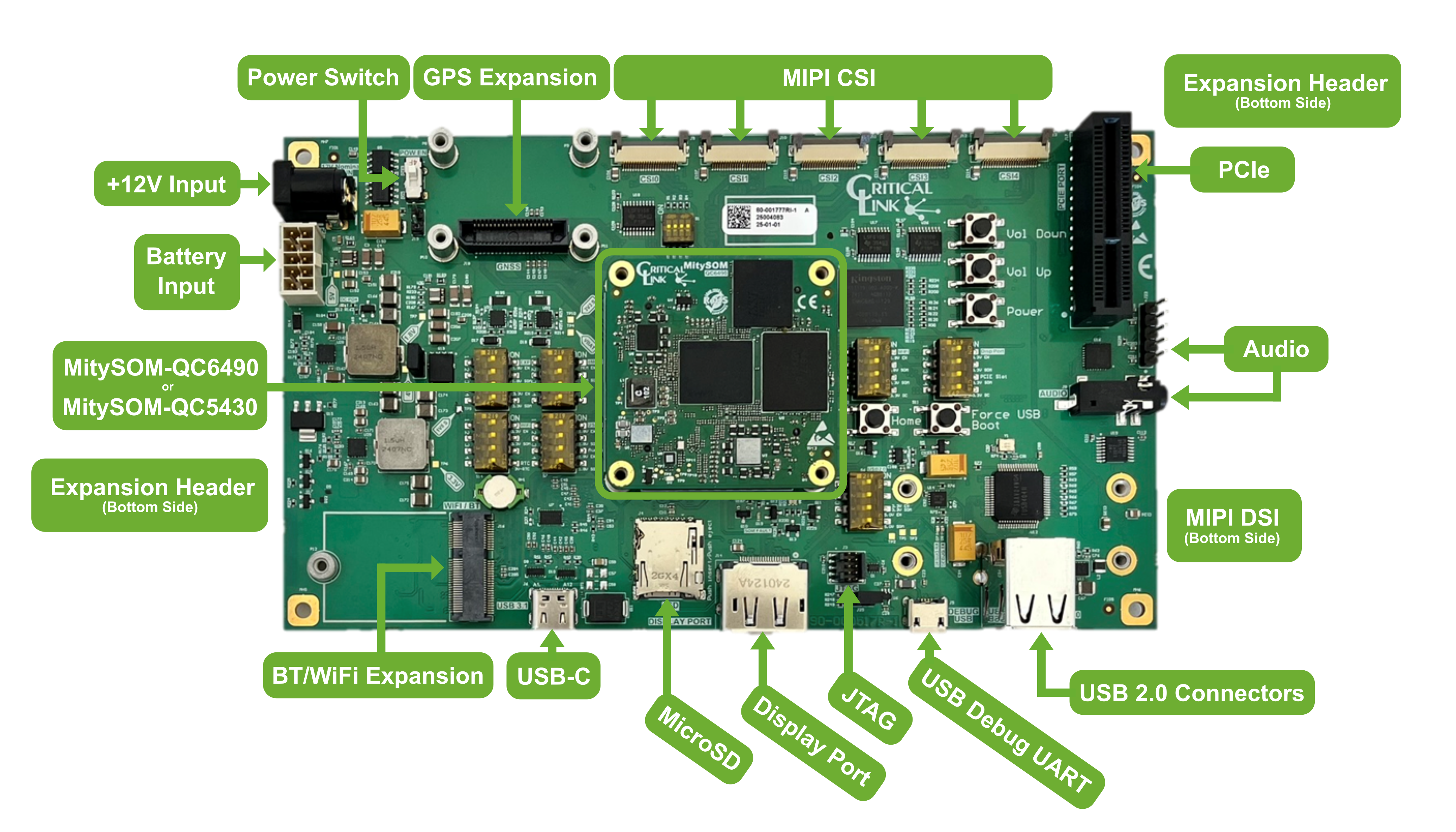
- The MitySOM-QC has three wafer level packages (outlined in red in the image below). Please take care to not touch or apply pressure to these packages when handling the SOM.
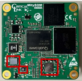
- Note that when removing the MitySOM-QC6490 the SOM should be removed by lifting up the left or right side first, as shown below. The Samtec SEARAY™ connectors can be "zippered" during mating/unmating.
Setting up the Development Kit
- Make sure Power Switch S13 is in the off position
- Make sure the Boot Mode Switches (S1) are set properly
- Currently all should be set to 0 as UFS is the only boot media supported at this time
- Make sure the Power Control Switches (S5-S10, S14) are set appropriately
- Please refer to the MitySOM-QC6490 Development Kit Datasheet for details on the supported switch settings.
- Connect the provided 12V Power Supply to barrel connector P1 on the top side of the development board
- Note: The provided power supply can provide up to 36 W. This is adequate for powering the MitySOM-QC6490 and most interfaces on the development kit. However, if a power hungry device is added to the PCIe slot a larger power supply may be required.
- Connect the development kit to a PC using provided USB micro cable to the USB Debug UART J5 on the top side of the development kit board
- On your PC open your preferred application for communicating with the Debug UART (e.g. putty, minicom, Tera Term, screen) at a baud of 115200
- Program the MitySOM-QC6490 with the latest by following the steps below
- Note that the MitySOM-QC6490 will come programmed, but this may not be the latest release.
- Build and Release information can be found in /etc/buildinfo
- CL_VERSION corresponds to the BSP Version
- IMAGE_BASENAME corresponds to the image version (e.g. qcom-multimedia-image)
Programming the MitySOM-QC6490
- Install the qdl tool from Qualcomm on your PC
- Download and unzip the latest BSP Release from Repositories and Pre-built Images
- Or follow the steps in Building and Customizing qcom-multimedia-image with Yocto to build the image from source.
- Connect the development kit to a PC using the provided USB-C cable to the USB-C port J6 on the top side of the SOM
- Set the Power Switch S13 to the On position
- Put the QCS6490 into QDL mode using one of the two following options:
- Press and hold the Power and the Force USB Boot buttons for 15 seconds
- Boot the SOM into Linux execute command
reboot edl- You can also execute via
adbwith commandadb shell 'reboot edl'
- You can also execute via
- Note that if you are running Linux on your PC you can use lsusb to verify the board is in QDL mode. Example output is below
$ lsusb | grep QDL
Bus 001 Device 077: ID 05c6:9008 Qualcomm, Inc. Gobi Wireless Modem (QDL mode)
- On your PC navigate to the image you want to program onto the MitySOM-QC6490
- qcom-multimedia-image
- A larger and more full featured image with camera, display, etc. support
- qcom-console-image
- A trimmed down image without camera or display support. Note: This image will be made avaialble in a future release
- qcom-multimedia-image
- Use the QDL tool to program the desired image
- Linux
$ ${PATH_TO_QDL}/qdl prog_firehose_ddr.elf rawprogram*.xml patch*.xml
- Windows
<pathToQDL>\QDL.exe prog_firehose_ddr.elf rawprogram0.xml rawprogram1.xml rawprogram2.xml rawprogram3.xml rawprogram4.xml rawprogram5.xml patch0.xml patch1.xml patch2.xml patch3.xml patch4.xml patch4.xml patch5.xml
- Linux
Booting the MitySOM-QC6490
- Set the Power Switch S13 to the On position
- Press and hold the Power button S2 for approximately 1 second
- Note that if you do not hold the Power button for long enough the boot process will stop and on USB Debug UARTyou will get an error message similar to the following:
Boot up PwrKey press 0 ms detected is less than expected 400 ms duration.
- Note that if you do not hold the Power button for long enough the boot process will stop and on USB Debug UARTyou will get an error message similar to the following:
- Once the boot process has completed successfully on USB Debug UART you should see the a login prompt similar to the following:
qcs6490-mitysom-devkit login:
- Login with the following credentials:
- login: root
- Password: oelinux123
Next Steps
Once you have MitySOM-QC6490 booting to Linux the following pages will give you more in depth details of what the MitySOM-QC and Development Board have to offer:
Software Development Related
Using Android Debug Bridge (adb) for Remote Access and File Transfers
Cross Compiling Hello World (C/C++) for the MitySOM-QC6490
Building and Customizing qcom-multimedia-image with Yocto
Configuring the QUP Ports (I2C, I3C, SPI, and UART)
Building and Customizing firmware
Update OS and Firmware via OSTree and Capsule Updates
MitySOM-QC Peripheral Related
UFS
Display Options
MIPI Cameras
Expansion Header (GPIO/SPI/I2C/UART/SWR/I2S)
Push Buttons
Wi-Fi
PCIe Gen 3 2-lane
microSD Card
eMMC
Audio
Remote Button and Power Control