Read PRU0 GPI Write PRU1 GPO
Overview
The goal of this example is to demonstrate multi-core communication between PRU0 and PRU1 on the Programmable Real-Time Unit (PRU) subsystem. In this scenario, we will use register R31 to generate General Purpose Input (GPI) interrupts within the PRU0 core. These interrupts will serve as signals to notify PRU1 that a push button event has taken place.
Once PRU1 receives the interrupt, it will respond accordingly to the event, allowing the two cores to coordinate their actions. Additionally, register R30 will be used to generate General Purpose Output (GPO) signals. These signals will be responsible for toggling the state of an LED connected to the system, providing visual feedback that the button press has been successfully detected and processed.
References
- https://software-dl.ti.com/processor-sdk-linux/esd/AM62X/10_01_10_04/exports/docs/common/PRU-ICSS/PRU-Hands-on-Labs.html#lab-2-read-push-button-switch-on-pru0-gpi-toggle-led-with-pru1-gpo
- https://www.criticallink.com/wp-content/uploads/MitySOM-AM62_Datasheet.pdf
Prerequisites
- Download and install Code Composer Studio v12.8.1
- Download and Install TI's Processor SDK v10.01.10.04
- Build the Linux_Kernel for the AM62xx
Project Setup
- The following material will be needed to complete this example
- MitySOM-AM62x
- MitySOM-AM62x Dev Board
- XDS200 Debug Probe
- Oscilloscope
- Two wire LED Bulb
- Male-to-male header wire
Complete Setup (Oscilloscope is out of picture)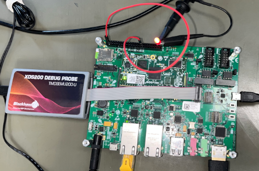
GPIO Expansion Close Up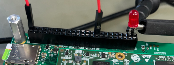
Insert the long wire of the LED into pin 3 and the shorter GND wire into pin 1.
For this example, we will be using a wire instead of a button. Insert one end of the wire into pin 17 and the other end into pin 45.
WARNING: Do not insert either end of the male-to-male header wire into pin 46, as it is a 12V supply and could damage the GPIO pin—or worse, the chip.
CCS Project Setup
Create two projects- Launch Code Composer Studio
- Navigate to File>New>CCS Project
- In the far right drop down next to target select "AM62"
- Select the PRU tab
- Name the project " button_led_0"
- Under "Project templates and examples" select "Empty Project"
- Select "Finish"
- Navigate to File>New>CCS Project
- In the far right drop down next to target select "AM62"
- Select the PRU tab
- Name the project " button_led_1"
- Under "Project templates and examples" select "Empty Project"
- Select "Finish"
- Right click on the button_led_0 project: toggle_led>right_click>Add Files
- Navigate to ~/ti-processor-sdk-linux-am62xx-evm-10.01.10.04/example-applications/pru-icss-6.1.0/labs/Hands_on_Labs/lab_2/solution/button_led_0/button_led_0.c
- Copy files and select "OK"
- Open button_led_0.c and make the following changes
/*TODO: Define GPI offset for SW1 */ - #define SW1 (1 << 5) + #define SW1 (1 << 7) ... /* Map event 16 to channel 1 */ - CT_INTC.CMR4_bit.CH_MAP_16 = 1; /*TODO: Select correct bit field and enter proper value */; + CT_INTC.CH_MAP_REG4_bit.CH_MAP_16 = 1; /*TODO: Select correct bit field and enter proper value */; /* Map channel 1 to host 1 */ - CT_INTC.HMR0_bit.HINT_MAP_1 = 1; /*TODO: Select correct bit field and enter proper value */; + CT_INTC.HINT_MAP_REG0_bit.HINT_MAP_1 = 1; /*TODO: Select correct bit field and enter proper value */; /* Ensure event 16 is cleared */ - CT_INTC.SICR = 16; /*TODO: Clear proper event */; + CT_INTC.STATUS_SET_INDEX_REG = 16; /*TODO: Clear proper event */; /* Enable event 16 */ - CT_INTC.EISR = 16; /*TODO: Enable proper event */; + CT_INTC.ENABLE_SET_INDEX_REG = 16; /*TODO: Enable proper event */; /* Enable Host interrupt 1 */ - CT_INTC.HIEISR |= (1 << 0); /*TODO: Enable proper event */; + CT_INTC.HINT_ENABLE_SET_INDEX_REG |= (1 << 0); /*TODO: Enable proper event */; // Globally enable host interrupts - CT_INTC.HIEISR |= (1 << 0); /*TODO: Enable proper event */; + CT_INTC.HINT_ENABLE_SET_INDEX_REG = 1; /*TODO: Enable global events */; - Ctrl-S to save the changes
- Right click on the button_led_1 project: toggle_led>right_click>Add Files
- Navigate to ~/ti-processor-sdk-linux-am62xx-evm-10.01.10.04/example-applications/pru-icss-6.1.0/labs/Hands_on_Labs/lab_2/solution/button_led_1/button_led_1.c
- Copy files and select "OK"
- Open button_led_1.c and make the following changes
/*TODO: Define toggling the BLUE LED */ - #define TOGGLE_BLUE (__R30 ^= (1 << 3)) + #define TOGGLE_BLUE (__R30 ^= (1 << 8)) ... /* Clear interrupt event */ - CT_INTC.SICR = 16; /*TODO: Clear event 16*/; + CT_INTC.STATUS_CLR_INDEX_REG = 16; /*TODO: Clear event 16*/; - Ctrl-S to save the changes
For both projects
Add the linker.cmd file- Right click on the project: project>right_click>Add Files
- Navigate to ~/ti-processor-sdk-linux-am62xx-evm-10.01.10.04/example-applications/pru-icss-6.1.0/labs/Getting_Started_Labs/linker_cmd/AM62x_PRU0.cmd
- Copy files and select "OK"
- In general, a .cmd file for PRU0 will be different from a .cmd file for PRU1. For this simple example, the same .cmd file could be used on either PRU processor. For your own applications, you may wish to find an example close to yours for the appropriate PRU and use the .cmd file for that example as a starting point.
- Right click on the project: project>right_click>properties
- In the Linked Resources window: Resource>Linked Resourcse
- Add New Path Variable: Name: PRU_SSP, Path: ~/ti-processor-sdk-linux-am62xx-evm-10.01.10.04/example-applications/pru-icss-6.1.0
- In properties window: Build>PRU Compiler>Include Options
- Under "Add dir to #include search path"
- Remove ${CCS_BASE_ROOT}/pru/include
- Add ${PRU_SSP}/include
- Add ${PRU_SSP}/include/am62x
- Under "Add dir to #include search path"
- Select "Apply and Close"
- In the Linked Resources window: Resource>Linked Resourcse
- In the toolbar select the hammer (Build 'Debug' for project 'toggle_led')
- There should be no errors, if errors do occur doubled check the include paths
Device Tree Modifications
In order to toggle Pin 3 in the GPIO expansion the following adjustments must be made in the arch/arm64/boot/dts/ti/k3-am62x-mitysom-devkit.dts
    main_gpio_p3_pins_default: gpio-p3-default-pins {
        pinctrl-single,pins = <
            /* P3 Connector */
-           AM62X_IOPAD(0x003c, PIN_INPUT_PULLDOWN, 7) /* (M25) GPMC0_AD0.GPIO0_15 */
+           AM62X_IOPAD(0x003c, PIN_INPUT, 1) /* (M25) GPMC0_AD0.PR0_PRU1_GPO8 */
            AM62X_IOPAD(0x0040, PIN_INPUT_PULLDOWN, 7) /* (N23) GPMC0_AD1.GPIO0_16 */
            AM62X_IOPAD(0x0044, PIN_INPUT_PULLDOWN, 7) /* (N24) GPMC0_AD2.GPIO0_17 */
            AM62X_IOPAD(0x0048, PIN_INPUT_PULLDOWN, 7) /* (N25) GPMC0_AD3.GPIO0_18 */
            AM62X_IOPAD(0x004c, PIN_INPUT_PULLDOWN, 7) /* (P24) GPMC0_AD4.GPIO0_19 */
            AM62X_IOPAD(0x0050, PIN_INPUT_PULLDOWN, 7) /* (P22) GPMC0_AD5.GPIO0_20 */
            AM62X_IOPAD(0x0054, PIN_INPUT_PULLDOWN, 7) /* (P21) GPMC0_AD6.GPIO0_21 */
-           AM62X_IOPAD(0x0058, PIN_INPUT_PULLDOWN, 7) /* (R23) GPMC0_AD7.GPIO0_22 */
+           AM62X_IOPAD(0x0058, PIN_INPUT, 5) /* (R23) GPMC0_AD7.PR0_PRU0_GPI7 */
            AM62X_IOPAD(0x0084, PIN_INPUT_PULLDOWN, 7) /* (L23) GPMC0_ADVn_ALE.GPIO0_32 */
Note: We use PIN_INPUT here instead of PIN_OUTPUT because setting the pinmux to input mode grants the pin both input and output capabilities, whereas output mode allows the pin to function only as an output.
Make sure to build these changes and push them to the board
Create and Launch Target Configuration
Connect the XDS200 Debug Probe to the Jtag port (J9) on the dev board
Create a new target configuration- Go to menubar>View>Target Configuration.
- Right Click on "User Defined" and select "New Target Configuration"
- Name the file AM62_XDS2XX.ccxml.
- Under the "General Setup" section, next to "Connection" open the drop-down arrow and select "Texas Instruments XDS2xx USB Debug Probe"
- Under the "General Setup" section, next to "Board or Device" scroll and select AM62.
- Click the "Save" button under the "Save Configuration" section.
- Select the "Test Connection" button to confirm the target configuration has been properly setup
- Name the file AM62_XDS2XX.ccxml.
- Right Click on "User Defined" and select "New Target Configuration"
- Go to toolbar>Debug>Debug Configuration
- Right Click on Code Composer Studio and select "New Configuration"
- Name the new configuration: button_led_x
- In the "Main" Tab
- Check "Use default target configuration"
- Next to "Target Configuration", select "File System" and select the AM62_XDS200.ccxml target configuration created in the previous step
- Deselect all CPU's except for "PRU_ICSS_PRU_0" and "PRU_ICSS_PRU_1"
- Click "Apply"
- In the "Program" Tab
- In the drop down box next to "Device" pick "Texas Instrument XDS2xx USB Debug Probe_0/PRU_ICSS_PRU_0"
- Next to "Project", click on "Workspace" and select "button_led_0"
- In the drop down box next to "Device" pick "Texas Instrument XDS2xx USB Debug Probe_0/PRU_ICSS_PRU_1"
- Next to "Project", click on "Workspace" and select "button_led_1"
- Click "Apply"
- In the "Main" Tab
- In the bottom right of the window hit "Debug"
The target configuration should now connect to both PRU's and load the button_led_0.out and button_led_1.out programs. To run these programs click on the "main() at button_led_X.c: ..." and hit the "Resume (F8)" button in the toolbar.
As you make have already observed from reviewing the code, the program is active low, which means the led will only toggle when the GPI voltage is unknown or grounded.
If the male-to-male header wire is connected to pin 45 the LED should stop blinking and remain at its last state (on or off). To toggle/blink the LED disconnect the wire from pin 45.
The LED should now be blinking, and the oscilloscope should show the GPIO’s voltage transitioning from high to low and low to high
Go to top

