Toggling GPIO with PRU GPO
Overview
General PRU Information
The PRU subsystem is designed with low latency and high determinism in mind. Unlike the ARM Cortex, it provides a direct path to its General Purpose Output (GPO) and General Purpose Input (GPI) signals. The PRU has 32 32-bit registers; for this example, we will focus only on R30, which controls the GPO signals. The PRU does not have any Network-on-Chip (NoC) infrastructure to obstruct signal integrity or reduce speed between its registers and pins. This design results in a drastic reduction in latency and virtually no output jitter due to its direct signal path.
Toggling GPIO with PRU GPO Information
In this example register R30 of the PRU_ICSS_PRU_0 will be used to communicate with GPIO0_15 on the MitySOM-AM62x GPIO expansion. An LED and oscilloscope will be used to show that the GPIO is being toggled properly, and signal communication has been established between the PRU and GPIO.
Debugging PRU with fputs Information
A hello world program has no useful purpose as an application program except for demonstrating that printf-like output is captured and made available within Code Composer Studio. This is an essential debug technique and that is the reason for this example. The PRU does not have a direct console which can capture the output. Code Composer offers an alternative in the form of CIO (Console IO). Using CIO, a program can make a call to fputs("message", stdout) and Code Composer can grab the message and display it in a Console View within Code Composer. This example will go through the steps needed to enable and make use of the CIO technique.
Note: The following instructions have been tested on SDK 10.01.10.04, and Code Composer Studio v12.8.1
References
- https://e2e.ti.com/support/processors-group/processors/f/processors-forum/1480168/processor-sdk-am62x-how-to-toggle-gpio-pin-by-pru-with-mcu-sdk/5684276#5684276
- https://e2e.ti.com/support/processors-group/processors/f/processors-forum/1269989/faq-what-is-a-pru-core-why-are-pru-gpio-signals-different-from-regular-gpios
- https://software-dl.ti.com/processor-sdk-linux/esd/AM62X/11_00_09_04/exports/docs/common/PRU-ICSS/PRU-Hands-on-Labs.html#lab-1-toggle-led-with-pru-gpo
- https://www.criticallink.com/wp-content/uploads/MitySOM-AM62_Datasheet.pdf
- AM62x TRM https://www.ti.com/lit/ug/spruiv7/spruiv7.pdf
Prerequisites
- Download and install Code Composer Studio v12.8.1
- Download and Install TI's Processor SDK v10.01.10.04
- Build the Linux_Kernel for the AM62xx
Project Setup
- The following material will be needed to complete this example
- MitySOM-AM62x
- MitySOM-AM62x Dev Board
- XDS200 Debug Probe
- Oscilloscope
- Two wire LED Bulb
- 200-400 ohm resistor (to reduce stress on the SOMs input/output)
Complete Setup (Oscilloscope is out of picture)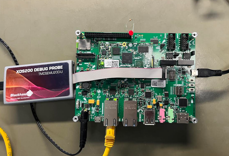
GPIO Expansion Close Up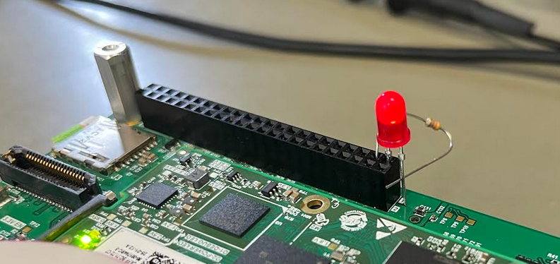
Insert one end of the 200-ohm resistor into pin 3 and the short leg (cathode) of the LED into pin 1. Then, connect the other end of the resistor to the long leg (anode) of the LED in series.
Note: A breadboard can be used to ensure wires do not disconnect throughout the lab
CCS Project Setup
Create the project- Launch Code Composer Studio
- Navigate to File>New>CCS Project
- In the far right drop down next to target select "AM62"
- Select the PRU tab
- Name the project "toggle_led"
- Under "Project templates and examples" select "Empty Project"
- Select "Finish"
- Right click on the project: toggle_led>right_click>Add Files
- Navigate to ~/ti-processor-sdk-linux-am62xx-evm-10.01.10.04/example-applications/pru-icss-6.1.0/labs/Hands_on_Labs/lab_1/solution/toggle_led/main.c
- Copy files and select "OK"
- Open main.c and make the following changes
 /*
 * main.c
 */
+// CYCLES_PER_SECOND will be same as speed of the processor
+#define CYCLES_PER_SECOND (250000000)
+#define CYCLES_PER_MS (CYCLES_PER_SECOND/1000)

int main(void)
- CT_CFG.GPCFG0 = 0;
+ CT_CFG.gpcfg0_reg = 0;
- __delay_cycles(100000000); // half-second delay
+ __delay_cycles(500*CYCLES_PER_MS); // half-second delay
- Ctrl-S to save the changes
- Right click on the project: toggle_led>right_click>Add Files
- Navigate to ~/ti-processor-sdk-linux-am62xx-evm-10.01.10.04/example-applications/pru-icss-6.1.0/labs/Getting_Started_Labs/linker_cmd/AM62x_PRU0.cmd
- Copy files and select "OK"
- In general, a .cmd file for PRU0 will be different from a .cmd file for PRU1. For this simple example, the same .cmd file could be used on either PRU processor. For your own applications, you may wish to find an example close to yours for the appropriate PRU and use the .cmd file for that example as a starting point.
- Right click on the project: toggle_led>right_click>properties
- In the Linked Resources window: Resource>Linked Resourcse
- Add New Path Variable: Name: PRU_SSP, Path: ~/ti-processor-sdk-linux-am62xx-evm-10.01.10.04/example-applications/pru-icss-6.1.0
- In properties window: Build>PRU Compiler>Include Options
- Under "Add dir to #include search path"
- Remove ${CCS_BASE_ROOT}/pru/include
- Add ${PRU_SSP}/include
- Add ${PRU_SSP}/include/am62x
- Under "Add dir to #include search path"
- Select "Apply and Close"
- In the Linked Resources window: Resource>Linked Resourcse
- In the toolbar select the hammer (Build 'Debug' for project 'toggle_led')
- There should be no errors, if errors do occur doubled check the include paths
Device Tree Modifications
In order to toggle Pin 3 in the GPIO expansion the following adjustments must be made in the arch/arm64/boot/dts/ti/k3-am62x-mitysom-devkit.dts
main_gpio_p3_pins_default: gpio-p3-default-pins {
    pinctrl-single,pins = <
        /* P3 Connector */
-        AM62X_IOPAD(0x003c, PIN_INPUT_PULLDOWN, 7) /* (M25) GPMC0_AD0.GPIO0_15 */
+        AM62X_IOPAD(0x003c, PIN_INPUT, 4) /* (M25) GPMC0_AD0.PR0_PRU0_GPO0 */
        AM62X_IOPAD(0x0040, PIN_INPUT_PULLDOWN, 7) /* (N23) GPMC0_AD1.GPIO0_16 */
        AM62X_IOPAD(0x0044, PIN_INPUT_PULLDOWN, 7) /* (N24) GPMC0_AD2.GPIO0_17 */
        AM62X_IOPAD(0x0048, PIN_INPUT_PULLDOWN, 7) /* (N25) GPMC0_AD3.GPIO0_18 */
        AM62X_IOPAD(0x004c, PIN_INPUT_PULLDOWN, 7) /* (P24) GPMC0_AD4.GPIO0_19 */
Note: We use PIN_INPUT here instead of PIN_OUTPUT because setting the pinmux to input mode grants the pin both input and output capabilities, whereas output mode allows the pin to function only as an output.
Make sure to build these changes and push them to the board
Create and Launch Target Configuration
Connect the XDS200 Debug Probe to the Jtag port (J9) on the dev board
Create a new target configuration- Go to menubar>View>Target Configuration.
- Right Click on "User Defined" and select "New Target Configuration"
- Name the file AM62_XDS2XX.ccxml.
- Under the "General Setup" section, next to "Connection" open the drop-down arrow and select "Texas Instruments XDS2xx USB Debug Probe"
- Under the "General Setup" section, next to "Board or Device" scroll and select AM62.
- Click the "Save" button under the "Save Configuration" section.
- Select the "Test Connection" button to confirm the target configuration has been properly setup
- Name the file AM62_XDS2XX.ccxml.
- Right Click on "User Defined" and select "New Target Configuration"
- Go to toolbar>Debug>Debug Configuration
- Right Click on Code Composer Studio and select "New Configuration"
- Name the new configuration: toggle_led_conf
- In the "Main" Tab
- Check "Use default target configuration"
- Next to "Target Configuration", select "File System" and select the AM62_XDS200.ccxml target configuration created in the previous step
- Deselect all CPU's except for "PRU_ICSS_PRU_0"
- Click "Apply"
- In the "Program" Tab
- Next to "Project", click on "Workspace" and select "toggle_led"
- Click "Apply"
- In the "Main" Tab
- In the bottom right of the window hit "Debug"
The target configuration should now connect to the board and load the toggle_led.out program. To run the program hit the "Resume (F8)" button in the toolbar.
The LED should now be blinking, and the oscilloscope should show the GPIO’s voltage transitioning from high to low and low to high
Debugging the PRU
This example will build upon the previous examples main.c and target configuration.
Update CCS Project Setup
Add fputs code to main.c
- The usual printf() function has a large memory footprint and is too large for use on a PRU. Alternatives exist in the form of fputs().
- Add the following code
- Include files
+ #include <stdio.h> + #include <stdlib.h> - Initial hello world message.
+ fputs ("Hello World from a PRU\r\n", stdout); - Periodic hello world message
    volatile uint32_t gpo;
+   int counter = 0;

...
     while (1) {
+        counter++;
+        if ((counter % 10) == 0) {
+            char buff[20];
+            ltoa (counter/10, buff, 10);
+            fputs(buff, stdout);
+            fputs(": another hello from the PRU\r\n", stdout);
+        }
- Include files
- Complete program should look like this:
#include <stdint.h>
#include <pru_cfg.h>
#include <stdio.h>
#include <stdlib.h>

volatile register uint32_t __R30;

/*
 * main.c
 */
// CYCLES_PER_SECOND will be same as speed of the processor
#define CYCLES_PER_SECOND (250000000)
#define CYCLES_PER_MS (CYCLES_PER_SECOND/1000)

int main(void)
{
    volatile uint32_t gpo;
    int counter = 0;

    /* GPI Mode 0, GPO Mode 0 */
    CT_CFG.gpcfg0_reg = 0;

    /* Clear GPO pins */
    gpo = 0x0000;

    fputs ("Hello World from a PRU\r\n", stdout);
    while (1) {
        counter++;
        if ((counter % 10) == 0) {
            char buff[20];
            ltoa (counter/10, buff, 10);
            fputs(buff, stdout);
            fputs(": another hello from the PRU\r\n", stdout);
        }
        gpo = __R30;
        gpo ^= 0xF;
        __R30 = gpo;
        __delay_cycles(500*CYCLES_PER_MS); // half-second delay
    }
}
- Heap size
- The default heap is 256 bytes. If the heap is not large enough, the fputs() will just silently fail and you will not see any output in Code Composer.
- You can turn off buffering using setvbuf() or you can make the heap larger.
- Right click on the project: toggle_led>right_clickProperties>PRU Linker>Basic Options
- Change the heap size to 1024
- Change the stack size to 1024
- The default heap is 256 bytes. If the heap is not large enough, the fputs() will just silently fail and you will not see any output in Code Composer.
- Click on Apply and Close
- In the toolbar select the hammer (Build 'Debug' for project 'toggle_led')
- There should be no errors, if errors do occur doubled check the include paths
Update the Target Configuration
For this example the AM62_XDS2XX.ccxml will be used as the target configuration
Update the Debug Configuration- Go to toolbar>Debug>Debug Configuration
- Select the "toggle_led_conf" configuration made earlier
- In the "Target" tab
- In the Device drop down select "Texas Instruments XDS2xx USB Debug Probe_0/PRU_ICSS_PRU_0"
- Under "Program/Memory Load Options" check off "Enable CIO function use (requires setting a breakpoint)"
- Click "Apply"
- In the "Target" tab
- In the bottom right of the window hit "Debug"
- Select the "toggle_led_conf" configuration made earlier
Debug the Program
The target configuration should be connected to PRU0, and the updated toggle_led.out should be loaded.
- Put breakpoint at start of while loop.
- Run->Resume
- Console should have the following output: "Hello World from a PRU message"
- Remove breakpoint
- Run->Resume
- Should see additional messages, about 1 every 5 seconds.
- Terminate debug session
Go to top

